Northeastern Electric Racing
Driver IO Dashboard

Driver IO Dashboard
Collaborated with electrical team to create master assembly of driver IO dashboard.
Helped position components in dashboard to follow given constraints.
3D Modeling from CAD Drawings


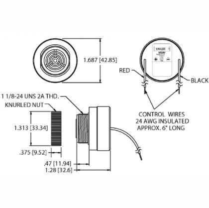
The electrical team needed 3D models of the button used for the driver IO dashboard so I used the spec sheet from the button to create an accurate model that was used for the master assembly.

The electrical team needed 3D models of the speaker used for the driver IO dashboard so I used the spec sheet from the speaker to create an accurate model that was used for the master assembly.
Master Assembly


My Role
Created 3D models of speaker and button used in master assembly.
Collaborated with electrical team to decide best placement of Arduino, H-bridge, and CAN module on CAN box and helped create holes in assembly for secure holding of components with screws.
Collaborated with electrical team to decide best placement of speaker and button on driver IO dashboard to meet with required constraints and created the holes for them in the dashboard so that we would be able to integrate them into master assembly.

Over-travel Switch Mount

Constraints
Constraint 1: A brake pedal over-travel switch must be installed on the car as part of the shutdown system and wired in series with the shutdown buttons (EV7.1). This switch must be installed so that in the event of brake system failure such that the brake pedal over travels it will result in the shutdown system being activated.
Constraint 2: Repeated actuation of the switch must not restore power to these components, and it must be designed so that the driver cannot reset it.
Constraint 3: The brake over-travel switch must not be used as a mechanical stop for the brake pedal and must be installed in such a way that it and its mounting will remain intact and operational when actuated.
Constraint 4: The switch must be implemented directly. i.e. It may not operate through programmable logic controllers, engine control units, or digital controllers .
Constraint 5: The Brake Over-Travel switch must be a mechanical single pole, single throw (commonly known as a two-position) switch (push-pull or flip type).

My Role
Research different types of switches and buttons that met the constraints.
Settled on a push button which had a big surface area so that it would be easy to activate and had a push-pull mechanism so that it would not be reactivated by driver.
Designed mount which screwed in to brake pedal mount easily and would support the button when the brake pedal smashed into it.

Initial Design
Created prototypes by 3D printing designs. This prototype features the mount which has a fitted slit for the button and allows easy access on the back for the electrical leads. It also has a lid which secures the button in place with 2 screws and 2 nuts. This prototype, however, lacked adjustability and due to changes in the master assembly, it needed to be changed.
Final Over-Travel Switch Design


Final Design
Due to the adding of different hydraulic cylinders I had to create a new design which fit into the master assembly and provided greater support to the over-travel switch.
This new design had more adjustability for the placement of the button since we do not know how far back the brake pedal will safely travel before we physically install and test it.
Had to include space for the brake lines to be installed through the over-travel switch mount.
